AppleCrate: An Apple II-Based Parallel Computer
Michael J. Mahon – July 26, 2004
Revised – May 9, 2010
Introduction
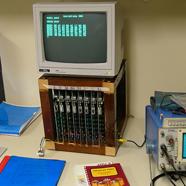
At the outset, when designing NadaNet, I envisioned that it could be used to support parallel computing on Apple II machines. To add more processors and save space, I decided that I would package several Apple //e main boards together, without keyboards or peripheral slot cards. (I didn’t disassemble the Apples myself, but found a box of Apple //e main boards being sold as an auction lot for about a dollar each!) I settled on a wooden cube about one foot on a side which I slotted to hold up to 8 main boards. For whimsical reasons, I called it an "AppleCrate".
Description
The boards are powered by a PC power supply (out of sight, with only its power switch showing in the picture). They are connected only to the network using the RCA connector on the lower right in front, described below. It is also possible to connect one or more monitors to their video ports, as shown in the picture.
I had originally hoped to use the board edge connectors (front edge) that Apple used at burn-in to power the boards, but discovered that different board revisions have different edge connections, and none have all the voltages normally supplied. I therefore decided to use threaded rods as power busses (on the bottom) and signal busses (on the top).
The usual mode of operation is to connect the AppleCrate to a more fully configured "master" Apple //e using NadaNet. The Master boots the eight Apples in the AppleCrate and uses them to do work. Once they have been booted and started, they can run independently of the master—though they are clearly I/O-constrained!
For testing and demonstration purposes, I have written several programs. The first was a parallel work simulator. The simulator puts independent "jobs" into a message queue of work to be done and receives "results" from a message queue of completed work. The parallel simulator is described in The AppleCrate Parallel Work Simulator. Another very useful program runs an Applesoft program on all AppleCrate slave machines, called BPRUN (Broadcast Parallel RUN). In addition, a File Server allows programs running on AppleCrate machines to use the server's ProDOS file system, without the need for a local operating system.
Indicators
It has proven useful to have some real-time indication of each board's activity. The stock board contains a red "power" LED (at the bottom) and a red "speaker" LED at the top. Both are easily visible from the back of the boards (the "front" of the AppleCrate). The function of the power LED is fixed, but the speaker LED is usable as an indicator that software running on the board can operate, just by toggling the speaker. For example, printing a "beep"—CHR$(07)—causes the speaker LED to flash for 0.1 second, and can be used to indicate some condition in the software.
Although the Applecrate network interface described below incorporates an LED to show global network activity, it is very useful to be able to see when any particular board is sending on the network. This need is met by using the PDL 3 timer to "stretch" each packet send operation into a visible flash of a green rectangular LED.
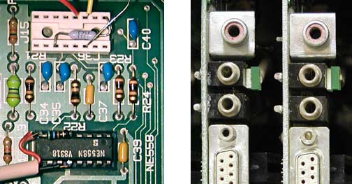
These photos show the modification made to the 558 timer chip, in which a 560 Ohm resistor is connected between pins 5 and 8, and the "send" signalling LED is connected between pins 8 and 12, with pin 8 being the anode. A resistor in the 100k-150k range is plugged into game port pins 1 and 11, to set the timing of PDL 3. The rectangular LED is attached to the cassette output jack with a strip of double-stick foam. In this way, the send LED is added without any modifications to the board itself.
Network Boot
Early in the design of the AppleCrate, it became clear that, since the machines would have no I/O capabilities other than the network, they would need to be booted from the network. This required that the ROMs on the boards be replaced with EPROMs containing modified RESET code to perform the network boot.
A study of the required code, and the easily replaceable code in the ROMs, suggested that replacement of the self-test code was the simplest path, since it is self-contained and contiguous. The Enhanced //e Cxxx-Dxxx ROM region contains $200 bytes of self-test code at $C600, while the unenhanced //e Cxxx-Dxxx ROM contains $400 bytes of self-test at $C400. Because the initial "active" network boot code required over $300 bytes, I decided to use modified Unenhanced Cxxx-Dxxx ROMs for the initial AppleCrate I.
Since the initial design, I changed the boot protocol to allow for much simpler "passive" boot code in ROM. This allowed the use of Enhanced ROMs as well as unenhanced ROMs, and as of NadaNet 3.1 it is the standard boot protocol, and all AppleCrates must use the new NadaNet 3.x passive boot ROMs.
The passive boot ROM (ORGed at $C400 for the unenhanced ROM) continuously monitors the network for a broadcast BOOTREQ control packet containing the load address and length of the immediately following boot code data. When the boot image has been correctly read from the network, control is passed to its starting address. This passive boot code only needs to read packets from the net, and so occupies about $190 bytes, which fits comfortably in any Apple //e ROM.
The new boot protocol capitalizes on the fact that boot code is sent as a broadcast transaction, so the machines being booted do not need IDs to receive boot code. A page of "second-stage boot code" is added at the front of the 'Crate machine boot image. This code is given control immediately after the boot image is received, and, when enabled by the "GETID daisy chain", it sends a GETID request to the machine that &BOOTed it, making use of the code in the full NadaNet boot image to do so (see the BOOT2 code in the NADA.CRATE listing for details).
The "GETID daisy chain" operates by having each machine, after successfully completing its GETID, enable the "next" machine to do its GETID. This is accomplished by having each machine initially set its AN2. Then, it waits until its PB2 is low, completes its GETID, and then drops its AN2, enabling the next machine. PB2 of each machine is connected to AN2 of the "previous" machine. The "first" machine is permanently enabled by connecting its PB2 to ground through a 4.7k resistor. This causes the permanent IDs to be assigned in the fixed order of the physical daisy chain, while allowing all ROMs to be identical.
The BOOTing machine's GETID service routine looks at the requesting ID, and if it is temporary (>127) it assigns the next available permanent ID and sends it in an ACK to the requesting machine. (If the sender already has a permanent ID, then it is simply returned in the ACK.) When each machine's GETID is successful, it drops its AN2, enabling the next machine. Then it clears its video display, writes a banner showing the machine ID, and enters its server loop.
When a network-booting machine is reset, it checks page 3 to see if it is being cold started or warm reset. If it is a warm reset, it re-enters its Server loop. If it is a cold start, it initializes and enters the ROM boot code, again waiting for a BOOTREQ packet.
AppleCrate Network Interface
NadaNet is a TTL-level serial network in which ONE is represented as a logic high (greater than +2 volts) and ZERO is represented as a logic low (less than +0.7 volts). The fanout capability of a TTL annunciator output is sufficient to drive a dozen or so TTL pushbutton inputs if they are not otherwise connected, as in the case of the early Apple II machines.
Although NadaNet began—and was named for—not requiring any extra hardware, some changes Apple made in the Apple //e pushbutton circuits necessitated hardware buffering.
The Open- and Closed-Apple keys on the post-][plus machines are connected to pushbutton inputs 0 and 1. In order to function in the same manner as game controller buttons, the keyboard contains 470-ohm pulldown resistors for each Apple key, and pressing the key connects the corresponding pushbutton input to +5 volts.
In addition, to support board self-test at the factory, the main board contains 11K pullup resistors pulling a keyboard-less pushbutton input to +5v.
The effect is that the pushbutton inputs on later machines are relatively low-impedance inputs, each of which sinks on the order of 10mA when driven high. While an annunciator output could drive one or two such inputs, any attempt to connect more than a small number of machines together directly would overwhelm the drive capability of the annunciator outputs of the machines.
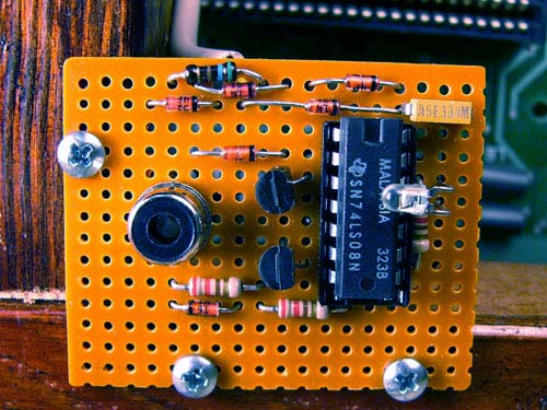
My solution was to add emitter followers to drive the pushbutton inputs and the network. These emitter followers are built onto a 16-pin header (or machined-pin socket) that plugs into the 16-pin game port and provides the network and ground wires to connect to the network bus.
When building the 8-board AppleCrate, I considered using eight of these network adapters, daisy-chaining them from board to board, and then on to the rest of the network. However, I soon realized that since the boards in the AppleCrate do not have keyboards connected, their pushbutton inputs are encumbered only by the 11K pullup resistors, for a total parallel pullup resistance of about 1.4K.
A single emitter follower with a low-value pulldown resistor easily drives this load. To collect the annunciator outputs, I decided on a distributed 8-input OR using 1N914 diodes connecting from the game connectors of the individual boards to a common bus.
The network adapter circuit for the whole AppleCrate is quite similar to a single Apple //e adapter:
Unlike the individual machine adapter, a 74LS08 has been used to standardize logic levels (which would otherwise suffer three diode drops) and to drive an LED indicating activity on the net.
Note that the buses and the network are clamped to stay within 0 to +5 volts. This was a precaution against ESD and minor "metallic mishaps" in its vicinity.
The 220 ohm network pulldown resistor in the AppleCrate interface is sufficiently low that no supplemental pulldown should be required if an AppleCrate is connected to the network.
Running Programs on AppleCrate
Programs are started on Applecrate from a master machine, which is also responsible for booting. The sample application BPRUN (Broadcast Parallel Run) demonstrates how any Applesoft program can be run on all serving AppleCrate machines. Of course, the program that is run is responsible for any further communication among the slave machines or between the slave machines and the master machine.