AppleCrate II: A New Apple II-Based Parallel Computer
Michael J. Mahon – July 26, 2008
Revised – September 23, 2015
Introduction
In 2004 I built the first AppleCrate, an 8-board system, as an inexpensive, easy to program vehicle for experiments in parallel programming—a kind of "blade server" for the Apple II, if you will! AppleCrate I (at the time I didn't realize that it was number "I" ;-) was great fun, and it enabled some very interesting experiments, but over time I discovered some of its shortcomings.
First and foremost, since the boards were supported by only two edges and not clamped in place, it was relatively fragile and hard to transport. Second, I had come across situations in which more than 8 slave processors would have been useful. Third, my arrangement for collecting audio signals synthesized by the slaves was quite makeshift and delivered sound with lots of digital "hash" as background noise. And finally, the original AppleCrate made no provision for plugging I/O cards into any of its boards, so it had to be hosted by a separate Apple II, adding to the problem of transporting it for demonstrations.
The AppleCrate II is designed to be significantly improved in all of the areas that were problems for the AppleCrate I.
Description
The AppleCrate II is made from 17 Enhanced Apple //e main boards. (Fifteen of these boards were obtained in the same eBay auction that netted the eight unenhanced boards for the original AppleCrate.) Because they are enhanced ROMs, the original NadaNet boot ROM code would not fit and a new boot protocol had to be developed, as described below.
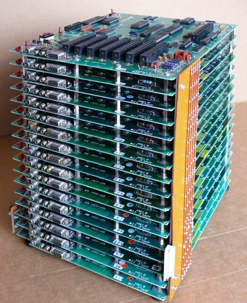
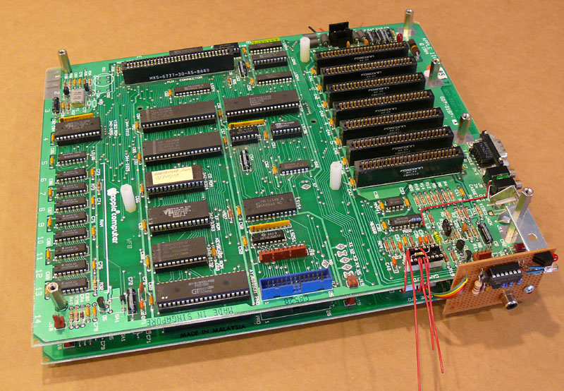
Instead of mounting the cards vertically in a frame, as in the original, I decided to mount them horizontally in a stack secured with standoffs—3/4" long hexagonal rods, each with a screw protruding from one end and a tapped hole in the other. The AppleCrate II has nine "columns" of these standoffs—six metal columns at the back and corners of the boards and three nylon columns interior to the boards to add stiffness, as shown in the photo below at the 2-board construction stage:
This "hi-rise" construction makes the "stack" quite rigid and sturdy, while eliminating the need for a space-consuming exoskeleton. It also has the advantage of leaving the top board unobstructed so that I/O cards can be plugged in, allowing it to serve as the host machine for the AppleCrate. (In fact, I used 17 boards so that the top board can serve as master and leave 16 slave machines for parallel programs.)
The Pushbutton 1 input and Annunciator 1 output bus wires and the AN2-to-PB2 GETID daisy chain wires are connected to machined-pin sockets inserted into the 16-pin game port connector. These connections support NadaNet, which is the only signal connection between the boards. The network adapter (described below) is shown with its mounting bracket under what will be the third board. The power bus card is supported by a similar angle bracket, and the standoffs immediately beneath them are filed down to accomodate the bracket thickness.
The boards are powered by a PC AT power supply. The average power consumed by an Apple //e board is about 4.2 watts, so the whole 17-board crate consumes only about 70 watts in total, and both the AppleCrate and the power supply run only a few degrees above ambient temperature.
I decided to use #12 copper bus wires to distribute power to all boards (visible on the right side of the first photo). I would have preferred a connectorized approach, but I could not come up with a connector scheme with a reasonable mating/unmating force. As a result, I decided to go with soldered power connections. (It's a good thing that Apple //e's are so reliable, since replacing one in the middle of the stack would be relatively difficult!)
The top board is used as the "master" machine with I/O cards and an external keyboard plugged into it. The Master boots the 16 slave Apples in the AppleCrate II and uses them to run parallel programs. Once they have been booted and started, they can run independently of the master—though they are clearly I/O-constrained!
Indicators
It has proven useful to have some real-time indication of each board's activity. The stock board contains a red "power" LED (at the right) and a red "speaker" LED at the left. Both are easily visible from the back of the boards (the "front" of the AppleCrate). The function of the power LED is fixed, but the speaker LED is usable as an indicator that software running on the board can operate, just by toggling the speaker. For example, printing a "beep"—CHR$(07)—causes the speaker LED to flash for 0.1 second, and can be used to indicate some condition in the software. (The speaker LED will not light when a speaker is installed, but AppleCrate boards have no speakers attached.)
Although the Applecrate network interface described below incorporates an LED to show global network activity, it is very useful to be able to see when any particular board is sending on the network. This need is met by using the PDL 3 timer to "stretch" each packet send operation into a visible flash of a green rectangular LED.
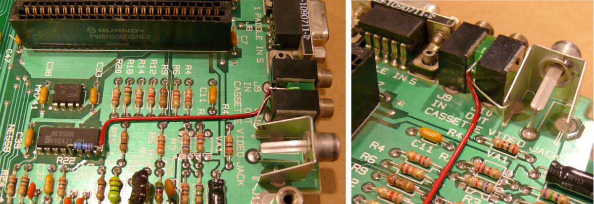
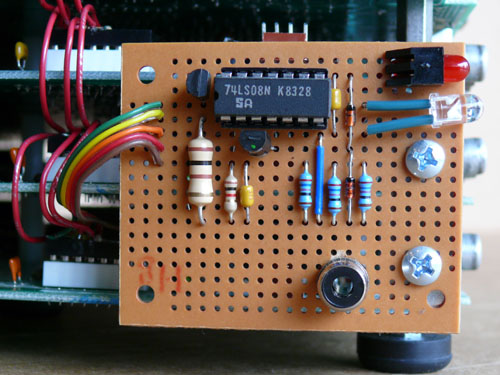
These photos show the modification made to the 558 timer chip, in which a 267-ohm resistor (just what I had handy—any value between 220 and 560 ohms is fine) is connected between pins 5 and 8, and the "send" signalling LED is connected between pin 8 and ground, with pin 8 going to the anode. The rectangular LED is carefully pressed between the cassette input and output jacks. On some boards, the jacks were so close together that it was necessary to "shave" the upper plastic swage on the side of the input jack with an Exacto knife to make room for the LED to press fit between them. (Note that in these photos the red wire connected to the anode of the LED has not yet been soldered.)
Network Boot in NadaNet 3.x
Since AppleCrate machines have no I/O capabilities other than the network, they must be booted from the network. This requires that the ROMs on the boards be replaced with EPROMs containing modified RESET code to perform the network boot.
As with the AppleCrate I, replacement of the self-test code was the easiest path, since it is self-contained, contiguous, and is executed upon power-on reset if no keyboard is connected. However, the Enhanced //e ROM contains only $200 bytes of self-test code, just half the size of the unenhanced //e self-test, requiring a new design for the network boot.
The AppleCrate I used an "active" boot protocol, in which each board enabled by the "GETID daisy chain" (connected from AN2 of the previous machine to PB2 of the current machine) continuously sent GETID requests to ID 1, until it was assigned a permanent ID and received a NadaNet boot image. The complexity of this protocol, requiring both sending and receiving packets over the network, resulted in a boot ROM requirement of almost $400 bytes—which fit in an Unenhanced //e ROM.
Since the Enhanced //e ROM has only $200 bytes available, a new "passive" boot protocol had to be devised. The new ROM code continuously monitors the network for a broadcast BOOTREQ control packet containing the load address and length of the immediately following boot code data. When the boot image has been correctly read from the network, control is passed to its starting address. This passive boot code only needs to read packets from the net, and so occupies just $190 bytes, which comfortably fits in place of the Enhanced //e ROM self-test code at $C600.
The new boot protocol capitalizes on the fact that boot code is sent as a broadcast transaction, so the machines being booted do not need IDs to receive boot code. A page of "second-stage boot" code is added at the front of the slave machine boot image. This code is given control immediately after the boot image is received, and, when enabled by the "GETID daisy chain", it sends a GETID request to the machine that &BOOTed it, making use of the code in the full NadaNet boot image to do so (see the BOOT2 code in the NADA.CRATE listing for details).
The GETID daisy chain functions just as it did in the AppleCrate I. The "first" machine is permanently enabled by connecting its PB2 to ground. AN2 of each machine is connected to PB2 of the "next" machine. The second-stage boot code running in each machine initially sets its AN2. Then it waits until it sees its PB2 go low, enabling it to send its GETID request. When its GETID is successful it drops its AN2, enabling the next machine. Then it clears its video display, writes a banner showing the machine ID, and enters its server loop.
This results in permanent IDs being assigned in the fixed order of the physical daisy chain, while allowing all ROMs to be identical. An LED on the AppleCrate II NadaNet adapter board is wired to the last machine's AN2, so that when the last machine drops its AN2, the red LED extinguishes, signalling that all machines have booted successfully.
When a network-booting machine is reset, it first checks the network state. If the network is low (ZERO), it performs a cold start. If the network is being held high (ONE), it checks page 3 to see if it is being cold started or warm reset. If it is a warm reset, it re-enters its Server loop. If it is a cold start, it initializes and enters the ROM boot code, again waiting for a BOOTREQ packet. (This approach has the advantage of reliably forcing a reboot on a power cycle, while still permitting boards to be warm reset while holding the network high.)
As of NadaNet 3.1, all AppleCrate boot ROMs must be NadaNet 3.x capable.
AppleCrate II NadaNet Interface
NadaNet is a TTL-level serial network in which logic high is represented by a voltage greater than +2 volts and logic low is represented by a voltage less than +0.7 volts. The fanout capability of a TTL annunciator output is sufficient to drive a dozen or so TTL pushbutton inputs if they are not otherwise connected, as in the case of the early Apple II machines. Although NadaNet began—and was named for—requiring no (nada) extra hardware, some changes Apple made in the Apple //e pushbutton circuits made hardware buffering necessary for these machines.
The Open- and Closed-Apple keys on the post-Apple ][plus machines are connected to pushbutton inputs 0 and 1. In order to function in the same manner as game controller buttons, the keyboard contains 470-ohm pulldown resistors for each Apple key, and pressing the key connects the corresponding pushbutton input to +5 volts. In addition, to support board self-test at the factory, the main board contains 11K pullup resistors to pull PB1 and PB2 pushbutton inputs to +5v on a board without a keyboard connected.
For the 17-board AppleCrate, since the 16 slave boards do not have keyboards connected, their pushbutton inputs are encumbered only by the 11K pullup resistors, for a total parallel pullup resistance of about 650 ohms. A single emitter follower with a low-value pulldown resistor easily drives all machines in parallel. To collect the annunciator outputs, I use a distributed 17-input OR using 1N914 diodes connecting from the game connectors of the individual boards to a common bus. As a result, a single adapter interfaces all 17 boards to NadaNet:
Unlike an individual machine adapter, a 74LS08 has been used to standardize logic levels (which would otherwise suffer three diode drops). One spare 'LS08 section is used to drive an LED indicating activity on the net. The final 'LS08 section is used to indicate when the last machine in the GETID daisy chain (machine #17) has dropped its AN2, meaning that all machines have booted successfully (the LED extinguishes when the GETID chain is complete).
Note that the network is diode-clamped between 0 and +5 volts as a precaution against ESD.
The 267-ohm network pulldown resistor in the AppleCrate interface is sufficiently low that no supplemental pulldown should be required even for long networks if an AppleCrate is connected to the network. (I should point out the the peculiarly specific value of the 267-ohm resistors is just a reflection of what was readily available to me—anything from 220 to 270 will work well.)
One interesting and entertaining use of an AppleCrate is as a multi-voice wavetable audio synthesizer.
An Apple //e only has 1-bit sound output built in, but with suitable programming (see AppleCrate Polyphonic Music Synthesizer), it is possible to create a 5-bit software digital-to-analog converter (DAC) with a sample rate of 11.025kHz and a pulse repetition rate of 22.05kHz. Performing wavetable sound synthesis with such a software DAC uses 100% of the processor cycles of an Apple //e, so each board of an AppleCrate can generate just one note of one instrument at any instant. For example, if a guitar is strummed, 6 oscillators must sound, one for each string. With 16 slave boards, the AppleCrate II can create 16-voice polyphony! Here is an example of the AppleCrate II performing "When I'm 64". (This recording is mono, though the AppleCrate ouput is stereo.)
The AppleCrate I had a very simple sound design: a 10K resistor connected each board's speaker output to a common mixing point with a 2.2k resistor to ground, shunted by a 0.1uF capacitor to form a single-pole low-pass filter. This design has several weaknesses. First, the speaker output pulses are derived from the +5v of each board, which is electrically noisy, and this noise finds its way to the mixer output. Second, with only a single mixing point, output was monaural. Third, the single-pole low-pass filter rolls off at only 6dB per octave, so that it is only partly effective at reducing the high-level 22kHz pulse component while also attenuating desired high frequencies in the synthesized sound. Finally, the output at the mixing point was low level, and required an external amplifier.
The AppleCrate II addresses each of these problems by adding an external sound processor box:
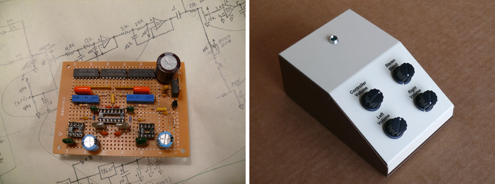
To reduce spurious noise, the sound output taken from each board is a TTL logic level, and each board's signal is separately passed through an inverter stage in the sound processor box. This inverter, like all the audio circuits in the box, is powered by a "quiet" +5v that is double-regulated down from the +12v supply of one of the boards. The resulting "clean" pulse-width modulated signals from the boards are then mixed.
The signals are mixed to two mixing points, with boards 1-9 going to the left channel and boards 10-17 going to the right channel, providing the capability of generating stereo sound. A Stereo Blend control is provided to permit blending the stereo channels to mono if desired. In addition, the signal from board 1, the master/controller machine, is provided with a separate mixer gain control, so that its output can be included or excluded from the outputs of the slave boards.
In place of the simple single-pole RC low-pass filter in the AppleCrate I, the sound processor provides 5-pole Sallen-Key low-pass filters for both left and right channels. The cutoff frequency of these filters is 5.5kHz, which reduces the level of 22kHz in the outputs by 60dB with negligible attenuation of valid high frequency signal components.
Finally, the output of the filters passes through left and right volume controls to two LM386 power opamps that drive small speakers or headphones directly. Stereo line-level outputs are connected prior to the volume controls.
The sound processor connects to the AppleCrate II through a ribbon cable and DB-25 connector that carries all 17 speaker channels plus +12v and ground (plus a few spare wires for future expansion).
For comparison with the AppleCrate I's 8-oscillator rendition of In My Life, here is the new AppleCrate II 13-oscillator version of In My Life requiring 13 oscillators (again, recorded in mono). Note that 13 oscillators are enough that no oscillators are "stolen" from sounding notes, so there are no missing notes in the bridge. (Spreading the music across more oscillators also relieved memory pressure sufficiently to add the final crash cymbal, which sounds for almost a second without repeating, and so requires more than 10KB of sample memory.)
Running Programs on AppleCrate
Programs are usually started on Applecrate from a master machine (usually ID 1), which is also responsible for booting. BPRUN (Broadcast Parallel RUN), runs a specified Applesoft program on all slave machines. The program that is run is then responsible for any further communication among the slave machines or between the slave machines and the master machine.
Some general purpose servers have been written to provide useful services to machines on NadaNet, including AppleCrate machines. The most fundamental is the Message Server, which is conventionally run on machine ID 2 to provide &PUTMSG and &GETMSG services as described in A Network Extension for Applesoft BASIC. Another very useful set of services is provided by the File Server, which offers most ProDOS file operations to all connected machines, whether they are running ProDOS, DOS, or no operating system at all (as with AppleCrate slave machines). Programs communicate with the File Server through a Message Server queue.
I have written several programs for testing and demonstration purposes. One of the most useful test programs is called RatRace, which enlists all the slave processors to pass thousands of messages through the Message Server (ID 2). An input message queue is assigned to each slave (IDs 3..17), and one slave "primes" the Message server with a message for each slave. Then each of the other slaves further loads the queues by sending three messages to random slaves. During the main phase of the program, each slave reads a message from its queue, ages it by one time unit, and, if it has not "expired", passes it on to a random slave's queue. The result is slave queue lengths rapidly bouncing around until all messages have timed out, as can be seen by plugging a monitor into the Message Server's video port.
This loads NadaNet to near maximum rates and serves as both a NadaNet and Message Server stress test. The run time of the test can be easily varied by changing the lifetime of messages and/or the number of messages initially queued. The message throughput is over 60 messages per second, even though each 20-byte message passes across the network twice, going to and from the Message Server.
In early 2015, I finally got around to daisy-chaining the AppleCrate I to the AppleCrate II, creating a 25-machine "AppleCrate". I made a video of this system running RatRace, which you can view here.
A simple little program that makes a nice demonstration and AppleCrate reliability test is CYLON. After it is BPRUN, each slave machine waits for a &POKE of a control value from a neighboring machine that specifies whether to pass the value on by &POKEing it to the next machine or the previous machine in ID sequence. It then flashes its speaker LED and returns to its &SERVE loop until the control value changes again. If it is the top slave (ID 2) or the bottom slave (ID 17), it reverses the direction indicated by the control value and &POKEs it accordingly. Inirtially, the top machine starts the process by &POKEing the control value "next" into ID 3.
The result of this logic is that a trail of about four speaker LEDs appears to oscillate down and up the AppleCrate endlessly, in a manner reminiscent of the eye of a (reclining) Cylon. (Four LEDs are lit because a "beep" flashes the LED for 100ms, and the control value has been &POKEd to four other machines in that time.)
If any &POKE fails while CYLON is running, the LED pattern stops, so running it for a few hours tests the reliability of an AppleCrate.
CYLON continues to run until the master machine is used to &BPOKE a zero ("stop") into the control value of all the serving slaves. A second &BPOKE is then required to end the program on the the four machines that were in the process of "beeping" their speaker LEDs instead of SERVEing when the first &BPOKE request was issued.
The purpose of constructing an AppleCrate is to support your own experiments in parallel program design. It is a quite general message-passing architecture, plus some "shared memory" primitives that are very Applesoft-friendly.